|
||||
The new software uses an AT89S4051 from Atmel. This CPU is an upgraded version of the "old" AT89C4051.
|
||||
For receiving packets adjust R18 to an DC voltage difference of 100 mV between pin 13 and pin 12 (the comparator inputs) of the AT89S4051.
|
||||
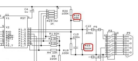
Part of the shematic with the modifications |
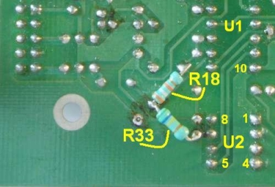
On the PCB component side remove the original R18 (50 KOhm variable resistor)
|
|||
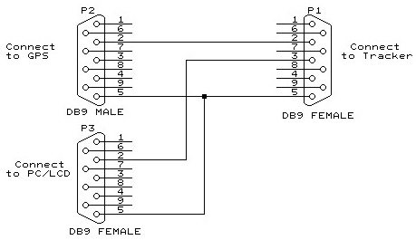
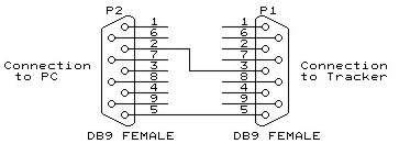
There are only 1 connector for RS232 on the tracker. In order to connect both a GPS and a
PC or LCD unit you must split the signals.
|
|
|
||
Interface cable between tracker and PC or LCD unit and GPS
|
Interface cable between tracker and PC or LCD.
|
|||
|
The above shown interfaces can not be used for programming the tracker For programming use the interface cable shown below connected directly to the Tracker P1. 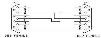
|
||||
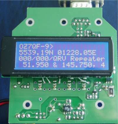
PCB with AT89C4051 showing the packets on
|
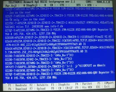
Communication program with a screendumb of received packets
|
|||
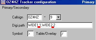
Setup program
There is a small "bug" in the Configuration Program. If you are using WIDEx-x
|
||||
|
After connecting power to the tracker the green and red LED will be flashing. The last LED lit shows the configuration used.
Green LED : configuration 1 Red LED : configuration 2 When the LEDs stops flashing the tracker sends a string out on the RS232 dataline (with 4800 Baud) : OZ4HZ APRS (RX) Tracker with 80S4051 ver 2.0 07 07 06 If the GPS unit is connected to the tracker it is powered up as well and the tracker will wait for approx. 30 sec for the GPS signals to get valid. If the GPSdata are valid a transmission takes place and the transmitted data are also send out on the RS232 dataline ie.: ) OZ4HZ>APTZ20,TRACE2-2:/102745h5541.90N/01230.41E-176/000 Tracker from OZ4HZ config 2 15 min fixed If you don't use SmartBeacon mode then ( and a receiver are connected to the tracker ) the received packet will be available on the RS232 dataline (some examples are shown below) : OZ1ISU-9>APZ100,OZ5DIB-1*,OZ4DIB-2*,TRACE4-3:!5556.37N/01216.87E>011/000/A=000234/QRV 434.850gilleleje pilot 82hz -2mhz OZ7QF-9>APZ100,RELAY,TRACE3-3:!5539.19N/01228.05E>000/000/QRV Repeater 51.950 & 145.750, 434.675, 1297.150 MHz OZ0CAB-7>APU25N,RELAY,TRACE3-3:@091019z5541.18N/01227.03E>161/024_OZ1IEP at his Taxi {UIV32} The normal function of the LEDs: Red LED : On for 50mS once every second On when TX are keyed Green LED : On with activated carrier detect or when receiving packets. On when TX keyed and data from GPS is OK. During normal operation you can switch to another configuration with the switch S1. The LEDs will flash and show the new configuration |
||||
 Monterings vejledning ver 2
 Setup program decription (pdf)
Setup program and decription (zip)
Ver 2 (rev. 2008-12-08) 8051 Assembler files (zip)
Ver 2 (rev. 2008-12-08) HEX file (zip)
Ver 2 (rev. 2008-12-08) HEX file for DJ7OO PCB (zip)
Setup program decription (pdf)
Setup program and decription (zip)
Ver 2 (rev. 2008-12-08) 8051 Assembler files (zip)
Ver 2 (rev. 2008-12-08) HEX file (zip)
Ver 2 (rev. 2008-12-08) HEX file for DJ7OO PCB (zip)
|
Ver 2 Schematic (pdf)
|
|||
| Home | ||||